Forum Discussion

 Occasional Contributor
How to simulate a design created in Platform Designer System
 3 years ago
Hi,
The testbench counter_fifo_tb.v that I sent to you before is just an example. If you want to get proper output waveform, you have to change a bit on the stimulus.
Below attached the edited testbench and proper output waveform image. As for the functionality, probably you still need to further verify from your side.
Thanks,
Best Regards,
Sheng
 Occasional Contributor
Hi Thank you very much!
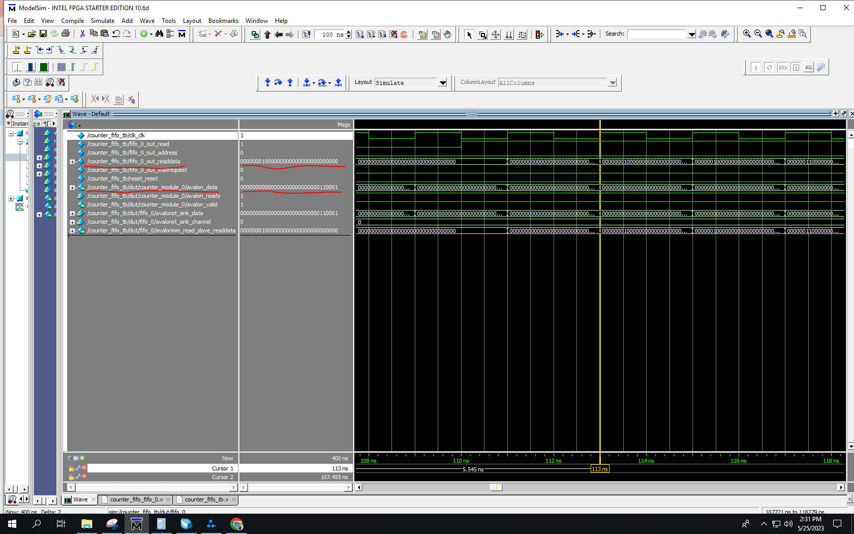
I have noticed that when I simulate just counter module (using counter_tb.v, that I attached in earlier message) the wave form of the data output (avalon_data) behaves as normal (have starting value 00000000000000000000000000000001) and starts the data with 32b'1 (please see attached Capture_wave_counter.PNG). But at the same time, when I simulate the counter_fifo with the testbench counter_fifo_tb.v . The fifo_0_out_readdata looks something different than the and the first entry is `00000001000000000000000000000000` (looks like counting started from the 8th bit. Please see the picture Capture_wave_counter_fifo.PNG). Also please see Counter_fifo_wave_1.PNG
Is it something to do with the FIFO parameter setting? You can see from the Counter_FIFO/counter_fifo.qsys file the parameters I used (also see the attached counter_fifo_qsys.PNG). I am just wondering that setting channel width parameter =8 in Avalon-ST Port settings of FIFO IP has to do something with this? (as you can see in counter.v, there is no signal named "channel" defined in it). I read from the FIFO IP manual that 'channel" signal is not mandatory one, and would like to make sure that the did not make any difference here.
I am wondering that whether is still missing?
Thanks again!