Mikexx Occasional Contributor
Occasional ContributorOccasional Contributor Regular Contributor
Hello,
Apologies for the delay and inconvenience caused. I can now focus for your issue.
Based on the parameters you provided, the VCO effective frequency is 450MHz, so there are 8 VCO periods for each 56.25MHz output clock. That means there are 64 phase shifts available for each of those 56.25MHz output clocks to roll through one output clock period. I say “effective” VCO frequency because in reality the VCO is running at 900MHz. 450MHz is lower than the supported VCO operating range, there is a post scale VCO counter that is often used to support lower frequencies, so it divides the VCO frequency in half. The compilation fitter report – PLL usage/summary will show the value of this post scale counter. For phase shift calculations, you use the VCO frequency reported by Quartus, which is after the VCO post scale counter, so 450MHz in this case.
You may be able to see a change after several phase shifts, but for accurate phase measurements you should route the clocks to I/O pins that can be scoped on the board. The phase shift resolution is 270ps, and you are sampling signal tap at a 4.4ns period, so you would need over 16 phase shifts to see a change in signal tap.
When implementing dynamic phase stepping, you can specify either an individual output clock, or all of the output clocks depending on what you drive to the cnt_select port of the PLL IP. Table 4 of AN 661 shows how to set the cnt_sel port. A value of 11111 shifts all of the output clocks simultaneously.
Occasional ContributorYes, you're entirely correct in that I have to perform multiple phase shifts (32) to invert a clock waveform. This is as expected and described in my post on the 25th September.
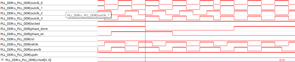
However, you seem to be answering a completely different question to the one posed, ie the predictability of which PLL clock is shifted with cntsel set to a known value. My post of the 6th October illustrates the issue, where if I should increment the phase with multiple phase shifts with cntsel[4:0] set to a specific value and noting which of the output's phase changes in sympathy.
For clarity I repeat below:
cntsel[4:0] = 0, outclk0 phase undergoes a change
cntsel[4:0] = 1, outclk4 phase undergoes a change
cntsel[4:0] = 2, outclk2 phase undergoes a change
cntsel[4:0] = 3, outclk5 phase undergoes a change
cntsel[4:0] = 4, outclk4 phase undergoes a change
cntsel[4:0] = 5, outclk3 phase undergoes a change
cntsel[4:0] = 6, no clock changes phase
cntsel[4:0] = 7, no clock changes phase
This is the issue at hand and look forward to your reply.