Forum Discussion

Altera_Forum Honored Contributor
11 years agoHonored ContributorBPSK Demodulation
Hello again, I am still struggling with BPSK demodulation :)
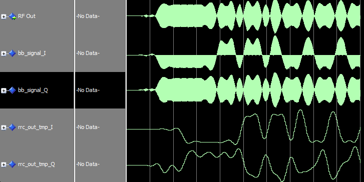
OK, now I am trying to implement Costas Loop for carrier synchronization, which involves Inphase and Quadrature Phase paths. Inphase is looking good, and works as expected, however, the Q component looks awkward. Take a look at these waveforms: http://www.alteraforum.com/forum/attachment.php?attachmentid=10363&stc=1 I understand that multiplying sin * cos will produce a high frequency component, which is a sin modulated by half amplitude of the data signal. BPSK(t) * sin(2*pi*f*t) = 0.5 * [DATA(t) * sin(0) + DATA(t) * sin(2*pi*f*t)] => 0.5 * DATA(t) * sin(2*pi*f*t) => LPF{0.5 * DATA(t) * sin(2*pi*f*t)} = 0 I feel that problem is in my LPF. I used the same Matched RRC filter that I used in the in-phase arm. Papers I read didn't mention that these two filters should be different, that's why I used the same filter. (I think those are unpractical DSP writers, KAZ :D ) So, should I use a separate Loop Filter for Q component? How do I determine it's parameters?66 Replies
 Altera_Forum--- Quote Start --- Hhhhhhhh What do you want Mr Kazem!!! Matlab is meant to prove math through math... not like ModelSim prove math through hardware, even though it's not giving correct results. Problem is either in the idea, or in our predictions. Idea is true since it's not that hard to write mathematical equations in Matlab. --- Quote End --- I don't quite understand your thoughts. Unless proved otherwise I believe strongly now that the free simplified documented design for BPSK carrier tracking does not work efficiently because the error of sin*cos is vague except at very start cycle of sine wave. This start is marred with filter delay and vanishes quickly. I suggets you use the costas loop for qpsk/qam which I did. This loop's error is based on slicer output. You will need to see diagrams of that loop which is based on complex multiplication with sliced values of I/Q together with signal I/Q to produce error. In your case you have only two sliced states either -1 or +1. So the concept of I/Q sliced data doesn't apply but may be you can use it but ignore the Q channel at the end. For QPSK it was particulary efficient. So I guess for BPSK as well. Try your skill again with modelling it that way. To slice the symbols you need to have threshold after matched rrc then feedback the results into error detector.
- Altera_Forum
Hhhhhhhh What do you want Mr Kazem!!! Matlab is meant to prove math through math... not like ModelSim prove math through hardware, even though it's not giving correct results. Problem is either in the idea, or in our predictions. Idea is true since it's not that hard to write mathematical equations in Matlab.
I have a question, how different is a Costas Loop for QPSK than BPSK? I think it should be the same with one difference, the quadrature component in BPSK has no information while it does have in QPSK, and it should not affect Costas Loop in both cases. Is this correct? - Altera_Forum--- Quote Start --- Thank you Mr KAZ. I hope you check that file and see if it can help to model our loop. (Actually it does have different behavior when you change - to + in error signal). --- Quote End --- I did some read on that file. This guy is probably funny trying to match some absolute phase of two signals. This is meaningless unless he got some specific application. absolute phase is meaningless to control as signal could arrive at any phase and this is immaterial in most radios (possibly all radios). what we want is to control frequency through phase until rf signal is centred on dc. Phase then doesn't matter and you should not compare phase if signals are of different frequencies. don't mix up with PLL that generate clock in phase with ref.
- Altera_Forum--- Quote Start --- freqz displays f normalised in radians so 1 means 0.5 of Fs and 0.3 means 0.15Fs. Your thinking is right about loop and if somebody wants to jam you on .15 then take him to court. If he is doing legally adjacent to your band then set your nominal nco to a closer start such as .20 i is index of sample (time/period) and phase then equals that index as part of the gang i*2*pi *inc for the cos/sin values. Time here has no meaning until you apply specific Fs. --- Quote End --- Thank you Mr KAZ. I hope you check that file and see if it can help to model our loop. (Actually it does have different behavior when you change - to + in error signal).
- Altera_Forum
freqz displays f normalised in radians so 1 means 0.5 of Fs and 0.3 means 0.15Fs.
Your thinking is right about loop and if somebody wants to jam you on .15 then take him to court. If he is doing legally adjacent to your band then set your nominal nco to a closer start such as .20 i is index of sample (time/period) and phase then equals that index as part of the gang i*2*pi *inc for the cos/sin values. Time here has no meaning until you apply specific Fs. - Altera_Forum
Hello Mr Kazem. Back to work :)
--- Quote Start --- the filter must pass dc but cut highband at 0.2 (of Fs) the function fir1 that I used cuts off at 0.3 of Nyquist (i.e. 0.3/2 of Fs = 0.15 so is just right for single tone). --- Quote End --- 1- I checked the frequency response of this filter using freqz. But it shows the cutoff frequency at 0.3 not 0.15. 2- Regarding the control of NCO, I just have this thought and please explain. If we control frequency as you suggest, suppose that the RF carrier is 0.2 and I tuned my radio to 0.1, the loop will push until it reaches 0.2, right? Will the loop span all the range from 0.1 to 0.2 to lock? Suppose there is another RF signal with carrier 0.15, don't you think it might lock on it while it's looking for 0.2? I just have this thought nagging on me for a while, I hope you explain it. 3- You told me that variable 'i' in the 'for' loop represents phase, why not time? 4- I attached a simulation of Costas Loop I found on MATLAB FileExchange. I hope you check it. - Altera_Forum
Thank you so much for bearing with me Mr Kazem.
I really got tired today, I'll see what I can do tomorrow and let you know. - Altera_Forum
the filter needs to cut off the high sidband.
rf signal has two frequencies at +0.1 and -0.1 when we mix it with 0.1 (or you can choose =-0.1) we get the sum and the difference: 0.1 + 0.1 = 0.2 (high sideband) 0.1 - 0.1 = 0 (our dream dc) the filter must pass dc but cut highband at 0.2 (of Fs) the function fir1 that I used cuts off at 0.3 of Nyquist (i.e. 0.3/2 of Fs = 0.15 so is just right for single tone). bwt this costas loop seems horrible to control compared to my previous work on qpsk/qam which was predictable. in this loop even if reverse the sense of error I get same result. so surely this is not how it should be done. If you make research and find out I will be interested to know. Should we use filter for the error (I tried IIR and IIR + a second accum and lost control). - Altera_Forum--- Quote Start --- 1- I ran your code for 12000 samples, output signal got distorted, why? 2- You are changing the frequency rather than shifting phase. Is it what you intend to do? My code controls phase not frequency. --- Quote End --- when you run nco you control the tuning word (phi_inc). That is what I am doing. phase and frequency are related. In design the nco will keep running nonstop from phase 1 and after some clocks (latency) its tuning word is updated. In the code the index i is the phase and it is incremented steadily. If you can run modelsim it gets much easier to check long sims and do any tweaks. The important thing initial is to watch the phi_in value tending towards the rf centre frequency. once it settles the signal will settle at a constant (dc). /2^16 is the tweek that turned out to control the loop better for our setup. you may require modifying it in final sign off of your radio ! output may look sinusoidal but check dynamic range (is it around zero or just osscilation around a constant level)
- Altera_Forum
1- I ran your code for 12000 samples, output signal got distorted, why?
2- You are changing the frequency rather than shifting phase. Is it what you intend to do? My code controls phase not frequency. 3- Why are you dividing by 2^16? 4- Phase, or more precisely, frequency is settling at 0.1, 0.11, 0.09 as you mentioned, but I don't see I&Q as DC... they are sinusoidal waves.