critical
602 Topics
Does Agilex™ 3 support SmartVID optional functions for some pin names in the Quartus® Prime Pro Edition Software?
Description Due to a problem in the Quartus® Prime Pro Edition Software version 25.1 for Agilex™ 3 FPGA devices, the Quartus® Prime Pro Edition Software incorrectly reports that SmartVID feature-related optional pin functions are available. The Agilex™ 3 FPGA devices do not support the SmartVID feature. The following pin functions are not available for the Agilex™ 3 FPGA devices: PWRMGT_SDA, PWGMGT_SCL, and PWRMGT_ALERT. Resolution For accurate pin information for the Agilex™ 3 FPGA devices, refer to the Agilex™ 3 FPGA Device Pin-Out Files, which are available from the Pin-Out Files for Altera® FPGAs. This problem is scheduled to be fixed in a future release of the Quartus® Prime Pro Edition Software.150Views1like0CommentsWhy do several IP design examples fail on the Agilex® 7 FPGA Series Transceiver SoC Development Kit?
Description The following IP Cores generate example designs for the Agilex® 7 FPGA Series Transceiver SoC Development Kit with incorrect VID settings. 1) Serial Lite IV IP 2) Interlaken (2nd Generation) IP 3) Triple-Speed Ethernet IP 4) E-Tile Dynamic Reconfiguration IP 5) E-Tile Hard IP for Ethernet and CPRI PHY IP 6) JESD204B IP 7) JESD204C IP 8) Ethernet Subsystem IP Resolution The correct VID settings can be found in section 6.1, Add SmartVID settings in the Quartus® Prime QSF file of the Agilex® F-Series Transceiver-SoC Development Kit User Guide. Update the design examples with the correct VID settings as shown below: set_global_assignment -name PWRMGT_BUS_SPEED_MODE "100 KHZ" set_global_assignment -name PWRMGT_SLAVE_DEVICE0_ADDRESS 42 set_global_assignment -name PWRMGT_SLAVE_DEVICE1_ADDRESS 00 set_global_assignment -name PWRMGT_SLAVE_DEVICE2_ADDRESS 00 set_global_assignment -name PWRMGT_SLAVE_DEVICE3_ADDRESS 00 set_global_assignment -name PWRMGT_SLAVE_DEVICE4_ADDRESS 00 set_global_assignment -name PWRMGT_SLAVE_DEVICE5_ADDRESS 00 set_global_assignment -name PWRMGT_SLAVE_DEVICE6_ADDRESS 00 set_global_assignment -name PWRMGT_SLAVE_DEVICE7_ADDRESS 00 set_global_assignment -name USE_PWRMGT_SCL SDM_IO0 set_global_assignment -name USE_PWRMGT_SDA SDM_IO12 set_global_assignment -name USE_CONF_DONE SDM_IO16 set_global_assignment -name VID_OPERATION_MODE "PMBUS MASTER" set_global_assignment -name PWRMGT_VOLTAGE_OUTPUT_FORMAT "LINEAR FORMAT" set_global_assignment -name PWRMGT_LINEAR_FORMAT_N "-13" set_global_assignment -name PWRMGT_TRANSLATED_VOLTAGE_VALUE_UNIT VOLTS This problem is scheduled to be fixed in a future release of the Quartus® Prime Pro Edition Software.214Views1like0CommentsWhy does the Quartus® Prime Pro Edition Programmer program pof file to DK-DEV-AGI027RBES unsuccessfully when following the R-Tile FPGA IP for Compute Express Link* (CXL*) Design Example User Guide?
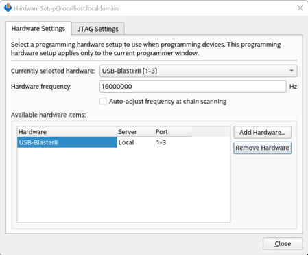
Description Due to a problem in the R-Tile FPGA IP for Compute Express Link* (CXL*) Design Example User Guide, version 1.10.0, you might observe pof programming failure on DK-DEV-AGI027RBES when following the chapter "C. Programming the Agilex™ 7 FPGA Development Kit with an External USB Blaster II", the description for the programming steps of DK-DEV-AGI027R1BES and DK-DEV-AGI027RBES is not separate and clear enough. Resolution To work around this problem, refer to the following instructions: 1. The programming steps for DK-DEV-AGI027R1BES: Connect an external USB blaster II into the J10- External JTAG header. Set the switch SW5.3 to ON (for the first time). Open the Quartus® Prime Pro Edition Software programmer tool. Click the Hardware Setup, and select USB Blaster II. Set the Hardware Frequency to 16000000Hz and uncheck the Auto-adjust frequency at chain scanning box. Click Close. Click Auto Detect and select MAX® 10 device, click OK. Right-click on the MAX® 10 device, and select Edit -> Change File. Select the MAX® 10 SOF file image: max10_bmc_avstx8_test.sof and click Open. Check the Program/Configure box and click Start to start the programming operation. When the operation is 100% successfully completed, click Auto Detect. Click Yes on pop-up windows. Right click on the QSPI_2Gb device, select Edit -> Change File. Select the POF file image: file.pof and click Open. Check Program/Configure box of QSPI_2Gb, P1, OPTION_BITS and click Start to start the programming operation. When the operation is 100% successfully completed, close the programmer window, shut down the platform (Pressing the on-off button on your server instead of typing “poweroff” in command window), set SW5.3 to OFF, disconnect USB Blaster II and boot the platform again. Type “lspci -vt ” in the command window, 0ddb device should be found. 2. The programming steps for DK-DEV-AGI027RBES: Plug in the USB cable to the USB port J8 (when using J10, DIPSWITCH SW5.3 (DK-DEV-AGI027RES and DK-DEV-AGI027R1BES) and SW8.3 (DK-DEV-AGI027RB and DK-DEV-AGI027-RA) should be off). Set the DIPSWITCH SW2 to [on:off:off:X] (the 4th bit is don't care). You can follow this combination which has been verified on the hardware: SW1=ON/Off/Off/Off; SW2=ON/Off/Off/Off; SW3=Off/ON/ON/Off; SW4=Off/Off/ON/Off; SW5=Off/Off/Off/Off; SW8=Off/Off/Off/Off Open the Quartus® Prime Pro Edition Software programmer tool. Click the Hardware Setup, and select USB Blaster II. Set the Hardware Frequency to 16000000Hz and uncheck the Auto-adjust frequency at chain scanning box. Click Close. Click Auto Detect to scan the JTAG devices. If the JTAG chain can not be detected, try setting SW4:3 to OFF. If a device called 1_BIT_TAP appears between AGIB027R29AR0 and VTAP10, ignore it and continue to the next step. Right click the VTAP10 device, Edit > Change Device, change it to MAX 10 > 10M50DAF256. Right click the 10M50DAF256 device, Edit > Attach Flash Device, select Quad SPI Flash Memory QSPI_2Gb. In the Programmer page, click QSPI_2Gb > Change File to select the .pof file. Start the Programmer. When the operation is 100% successfully completed, close the programmer window, and shut down the platform (Pressing the on-off button on your server instead of typing “poweroff” in the command window), if SW4:3 was OFF before, set it to ON, disconnect USB Blaster II and boot the platform again. Type “lspci -vt ” in the command window, 0ddb device should be found.622Views1like0Comments