Forum Discussion
Altera_Forum Honored Contributor
9 years agoHonored ContributorTiming Violations workaround strategy
Hello, Probably I didn't properly define timing constraints ... TimeQuest reported quite a lot of timing violations. In this connection I have one question - does exist some straightforward a...
.jpg)
Altera_ForumHonored Contributor
9 years agoHonored ContributorFirst, thank you for feedback Ryan.
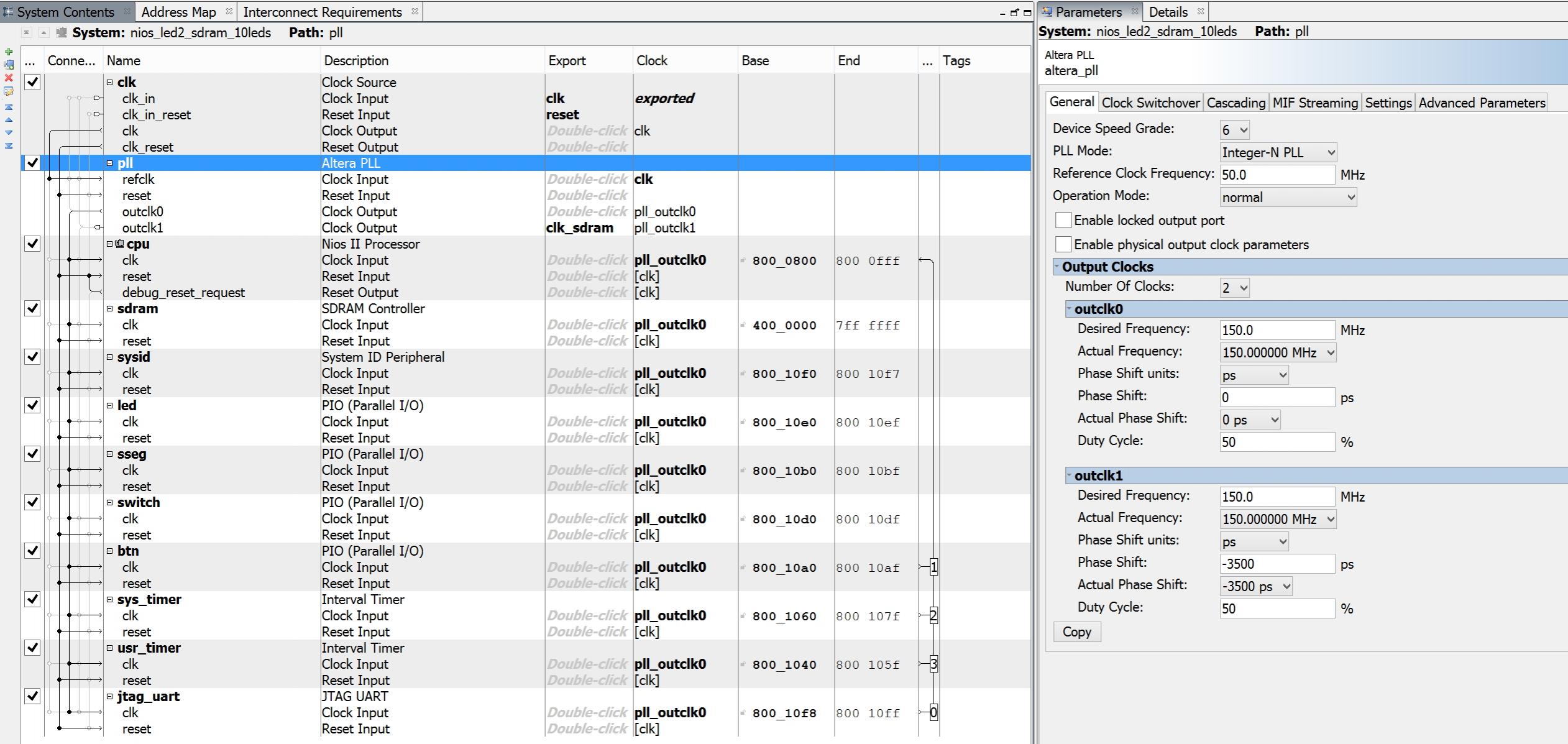
My case seems to be quite simple ... instantiation of one Qsys module. The Qsys module consists of (please have a look at Qsys screenshot below):- CPU
- PLL, that generates 2 clocks (1st – for all internal blocks, including CPU, 2nd – for external SDRAM)
- SDRAM controller, connected to external SDRAM
- GPIOs (buttons, switches, LEDs, 7-segment LEDs)
- 2 timers
module nios_led2_top (input clk,
	input  sw,
	input  key,
	output  led,
	output  hex3, hex2 , hex1, hex0,

	output  sdram_addr,
	inout  sdram_dq,
	output  sdram_bank,
	output sdram_cas_n, sdram_ras_n, sdram_cke, sdram_cs_n, sdram_clk,
	output sdram_dqmh, sdram_dqml, sdram_we_n);

	wire  sseg;
	assign hex3 = sseg;
	assign hex2 = sseg;
	assign hex1 = sseg;
	assign hex0 = sseg;

   nios_led2_sdram_10leds u0 (
		  .btn_export       (key),
		  .clk_clk          (clk),
		  .led_export     (led),
		  .reset_reset_n    (1'b1),
		  .sdram_wire_addr  (sdram_addr),
		  .sdram_wire_ba    (sdram_bank),
		  .sdram_wire_cas_n (sdram_cas_n),
		  .sdram_wire_cke   (sdram_cke),
		  .sdram_wire_cs_n  (sdram_cs_n),
		  .sdram_wire_dq    (sdram_dq),
		  .sdram_wire_dqm   ({sdram_dqmh, sdram_dqml}),
		  .sdram_wire_ras_n (sdram_ras_n),
		  .sdram_wire_we_n  (sdram_we_n),
		  .sseg_export      (sseg),
		  .switch_export    (sw),
		  .clk_sdram_clk    (sdram_clk)
    );
endmodule
create_clock -name clk -period 20
create_clock -name {altera_reserved_tck} -period 40 {altera_reserved_tck}
derive_pll_clocks
derive_clock_uncertainty
set_input_delay -clock altera_reserved_tck -clock_fall 3
set_input_delay -clock altera_reserved_tck -clock_fall 3
set_output_delay -clock altera_reserved_tck 3
create_generated_clock -name clk_ext_sdram -source .gpll~PLL_OUTPUT_COUNTER|divclk}]
set_false_path -to
#  Constraint SDRAM DATA for input
set_input_delay -clock clk_ext_sdram -max 0 ]
set_input_delay -clock clk_ext_sdram -min 0 ]
#  Constraint SDRAM DATA for output
set_output_delay -clock clk_ext_sdram -max 0 ]
set_output_delay -clock clk_ext_sdram -min 0 ]
#  Constraint DRAM ADDRESS for output
set_output_delay -clock clk_ext_sdram -max 0 ]
set_output_delay -clock clk_ext_sdram -min 0 ]
#  Constraint SDRAM Controlss for output
set_output_delay -clock clk_ext_sdram -max 0  sdram_dqm* sdram_cas_n sdram_ras_n sdram_cke sdram_cs_n sdram_we_n}]
set_output_delay -clock clk_ext_sdram -min 0  sdram_dqm* sdram_cas_n sdram_ras_n sdram_cke sdram_cs_n sdram_we_n}]
set_multicycle_path -setup -to }] 2
set_multicycle_path -hold -to }] 1
set_false_path -from
set_false_path -from
set_false_path -from * -to
set_false_path -from * -to