Forum Discussion

 Occasional Contributor
Timing Violations in JTAG Signals
 1 year ago
After internal testing and discussion, we’ve confirmed the following for Arria 10 devices:
- Only the on-board USB-Blaster II is capable of supporting up to 24 MHz.
- The off-board USB-Blaster II cannot reach 24 MHz due to certain limitations
- That said, if the TDO pin of the Arria 10 is driving the TDI of another device through a short trace, it can still support up to 24 MHz.
In the SDC files, you’ll notice a placeholder such as <<customer here>>. This needs to be updated based on the actual trace length measurements on your board. If you're targeting 24 MHz, the timing constraints will need to be tighter to meet the higher frequency requirements.
I'll attach a sample SDC file that helps close timing at higher speeds. Let me know if you have any further questions.
 Occasional Contributor
I am a bit confused about the recommended jtag.sdc file:
in the top function set_jtag_timing_constraints the default is to use separate timing constraints for analysis and fitter. As I understand the related comment this is the recommended default:
    # If the timing characteristic outside of FPGA is well understood, and
    # there is a need to provide more slack to allow flexible placement of
    # JTAG logic in the FPGA core, use the timing constraints for both
    # timing analysis and fitter; otherwise, use the default fitter timing
    # constraints.

    # ---customize here---
    set use_fitter_specific_constraint 1
However in the set_default_quartus_fit_timing_directive function the JTAG clock is fixed to 33 MHz (which is the max. Arria 10 supports)
proc set_default_quartus_fit_timing_directive { } {
    # A10 supports max 33.3Mhz clock
    set jtag_33Mhz_t_period 30

    create_clock -name {altera_reserved_tck} -period $jtag_33Mhz_t_period [get_ports {altera_reserved_tck}]
    set_clock_groups -asynchronous -group {altera_reserved_tck}
    # Force fitter to place register driving TDO pin to be as close to
    # the JTAG controller as possible to maximize the slack outside of FPGA.
    set_max_delay -to [get_ports { altera_reserved_tdo } ] 0
}
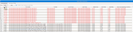
In the end this gives me the timing errors, even if I change the Blaster frequency to 16 MHz in set_tck_timing_spec
proc set_tck_timing_spec { } {
    # USB Blaster 1 uses 6 MHz clock = 166.666 ns period
    set ub1_t_period 166.666
    # USB Blaster 2 uses 24 MHz clock = 41.666 ns period
    set ub2_default_t_period 41.666
    # USB Blaster 2 running at 16 MHz clock safe mode = 62.5 ns period
    set ub2_safe_t_period 62.5

    # ---customize here---
    set tck_t_period $ub2_safe_t_period

    create_clock -name {altera_reserved_tck} -period $tck_t_period  [get_ports {altera_reserved_tck}]
    set_clock_groups -asynchronous -group {altera_reserved_tck}
}
To me it seems strange to have 2 separate constraints for the same clock for analysis and fitter.
- Could you please explain what's the reason for this?
- Is it intended to adjust the clock constraint in set_default_quartus_fit_timing_directive when changing the JTAG Frequency? if yes why is it using separate functions to set the clock. If no then I still have the problem with the timing errors!
Thanks for your help
best regards
Fabian


