Forum Discussion

Altera_Forum's avatar
Altera_Forum
Icon for Honored Contributor rankHonored Contributor
15 years ago

Missing Source Error - Buses & Nodes = Help!

Hi there, I'm currently doing a project for my Digital Systems course. I'm fairly new to Quartus and am attempting to compile a simple 4 Bit BCD Adder using block diagrams.

I was hoping that someone could describe to me why I cannot do this (I believe the problem area is highlighted):

http://img.photobucket.com/albums/v232/MasterChief117/problem.png

When I try and compile, it gives me:

error: node "i[1]" is missing source

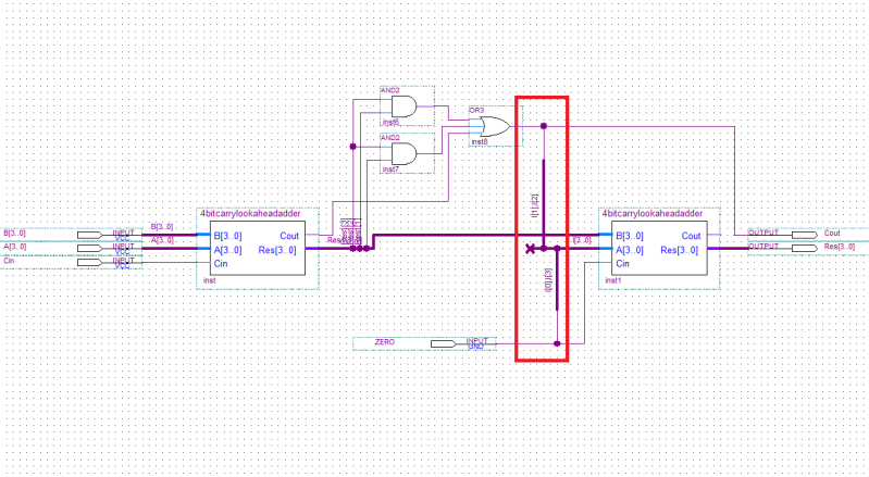
error: node "i[2]" is missing source

error: node "i[0]" is missing source

error: node "i[3]" is missing source

All I want is to have I[3],I[0] at 0 permanently, and I[1],I[2] read the value the output of the OR gate. Any pointers?

Thanks in advance,

Andrew

4 Replies

  • Altera_Forum's avatar
    Altera_Forum
    Icon for Honored Contributor rankHonored Contributor

    You can do this way, for example:

    Name the wire connected to the ZERO input pad as "zero"

    Name the OR gate output as "out_or"

    Draw a piece of conduit from the A[3:0] input port of adder but DON'T connect it to anything else; rename it as "zero,out_or,out_or,zero"
  • Altera_Forum's avatar
    Altera_Forum
    Icon for Honored Contributor rankHonored Contributor

    In schematic design, you can use the wire and constant symbols to connect the inputs as required.

  • Altera_Forum's avatar
    Altera_Forum
    Icon for Honored Contributor rankHonored Contributor

    --- Quote Start ---

    In schematic design, you can use the wire and constant symbols to connect the inputs as required.

    --- Quote End ---

    Thank you very much both of you. I'm just tried the method with constant and wire. I feel like a bit of a fool asking, but I'm having trouble figuring out how to use the constant symbol. It doesn't appear to take to wires. I tried assigning it to some named wires but got compilation errors saying some of my wires didn't have inputs. Would you be able to offer a brief explanation on how to use it? Google and forum searches are coming up empty.

    Thanks!!
  • Altera_Forum's avatar
    Altera_Forum
    Icon for Honored Contributor rankHonored Contributor

    My suggestion was to use constant to supply constant values and wirre to connect different nets. But instead of constant, you also have GND and VCC for 0 and 1 binary values.

    Schematic entry is perfect WYSIWYG, just play around and figure it out.