Forum Discussion

Altera_Forum's avatar
Altera_Forum
Icon for Honored Contributor rankHonored Contributor
11 years ago

button with fpga pull up, gnd

I connected push button to gpio_1 pins on Altera DE2 board.

In verilog code I assigned one button pin 'r' as ouput to gnd, another pin 'c' inout tri1 (pull up).

I want to make inverter for 'c' to drive any of DE2 onboard LEDS, when button pressed LED would lit.

module link_klavos2 (q, c, r );

output q;

inout tri1 c;

output r;

supply0 gnd;

assign r = gnd;

assign q = ~c;

endmodule

In Aldec-HDL environment I got compiled, but in Quartus it wont synthesize, error:

Error (10664): Bidirectional port "GPIO_1[35]" at main3.v(35) directly or indirectly feeds itself
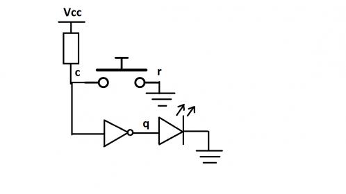
3 Replies

  • Altera_Forum's avatar
    Altera_Forum
    Icon for Honored Contributor rankHonored Contributor

    You need to post more (all) of your code - what you've posted has mistakes in but the error relates to something you haven't posted. Post the whole of main3.v, preferably wrapped in QUOTE tags...

    Cheers,

    Alex
  • Altera_Forum's avatar
    Altera_Forum
    Icon for Honored Contributor rankHonored Contributor

    Thanks for reply. My task is to connect a button to fpga port, configure one pin as GND, other as pull up, and drive a LED depending on button state. I attached picture illustrating it.

    Problems is that I don't know how to correctly assign pull up.

    I tried using tri1 with directions:

    output - measured 3.333V. LED all time off.

    input - measured 3V. When button not pressed - LED off, when pressed On.

    inout - measured ~200mV. When button not pressed - LED off, when pressed On. It works, but even if I touch the pins metal with finger, the LED turns on.

    At last I got It woking as input.

    Iam using Aldec- HDL, in block diagram I changed pin direction in module and terminal direction equally.

    module link_klavos2 (q, c, r );

    output wire q;

    inout tri1 c;

    output reg r;

    initial begin r = 0; end

    assign q = ~c;

    endmodule
  • Altera_Forum's avatar
    Altera_Forum
    Icon for Honored Contributor rankHonored Contributor

    I recommend not trying and implement the internal pull-up in your source code. I don't think Quartus does anything with it.

    Assuming you're using a DE2 board with a Cyclone IV device - in Quartus, in the Pin Planner, in the row with your 'c' signal in you need to turn the internal pull-up 'on'. Do this in the 'Weak Pull-Up Resistor' column. If you can't see this column by default right click anywhere in the column headings and select it to make it visible.

    If it's a DE2 board with a Cyclone II device you can't do this.

    Cheers,

    Alex