Altera_Forum Honored Contributor
Honored ContributorHonored ContributorWhen I use the Megafunction wizard to make a 10 bit shift register, the result does not have the I/O lines connected and there is what looks to be a table inside the design. I am not able to connect nodes to this part. What am I missing? I also have a 10 bit counter that behaves the same way.
Honored ContributorI'm not using schematic entry usually, but if I go to the schematic entry symbol tool and select a lpm_shiftreg MegaFunction, I can't manage to create a block symbol without in- or outputs. I really wonder, how you achieved it?
Honored ContributorThe design is set up as a project for the Max II family (EPM240). Is the limitation due to that? As far as creating the part, I just used the Wizard and entered '10' as the number of bits. If I change it to 8, it works fine.
Honored ContributorThere's no difference between FPGA and MAX II in this regard. I think, it's just some confusion in handling the MegaWizard tool.
Honored ContributorSo, tonite everything is working perfectly. I have no explanation except that it is Friday and some software elf finally decided to get to work. I will say that yesterday, Quartus was a fresh install, and maybe it took several invocations before the bits got connected.
Honored Contributor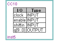