Forum Discussion

HY68 New Contributor
7 years agoNew ContributorUsing DDIO_In to read ADC data and timing analysis
Hi, I'm trying to use DDIO to capture ADC LVDS data from ADC3224. The device is set at 2 wires(x6) mode. The FPGA is Arria10(10AX027) and running at 100MHz sampling rate, which makes the ADC_FCLK...

KhaiChein_Y_Intel Regular Contributor
7 years agoRegular ContributorHi,
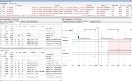
I checked in the Timing Analyzer. The register is located within the I/O. According to the user guide https://www.intel.com/content/dam/www/programmable/us/en/pdfs/literature/ug/ug_altera_gpio.pdf, you may set the delay elements manually in the Intel Quartus Prime settings file (.qsf).
Input Delay Element
set_intance_assignment –to <PIN> -name INPUT_DELAY_CHAIN <0..63>
Output Delay Element set_intance_assignment –to <PIN> -name OUTPUT_DELAY_CHAIN <0..15>
Output Enable Delay Element
set_intance_assignment –to <PIN> -name OE_DELAY_CHAIN <0..15>
You may try to set the max and min value and see if it helps the timing.
Thanks.

