Forum Discussion

 New Contributor
Problem with the clock of the 10M08SCE144
 2 years ago
Hi,
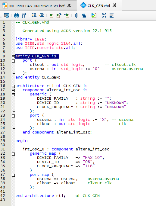
internal oscillator has an only roughly defined frequency, datasheet says min. 55, typ. 82, max. 116 MHz. Measured 84 MHz corresponds nicely to typical value. Specifying a different value in component instantiation has no effects on hardware, only in simulation.
To understand why you see sine waveform on oscilloscope, we need to know about IO standard and probing details. Unloaded pin waveform is basically a square wave, I guess you have low drive strength (e.g. 2 mA) and high load capacitance, e.g. 1:1 passive probe or direct connected coax cable.
 Super Contributor
Hi,
internal oscillator has an only roughly defined frequency, datasheet says min. 55, typ. 82, max. 116 MHz. Measured 84 MHz corresponds nicely to typical value. Specifying a different value in component instantiation has no effects on hardware, only in simulation.
To understand why you see sine waveform on oscilloscope, we need to know about IO standard and probing details. Unloaded pin waveform is basically a square wave, I guess you have low drive strength (e.g. 2 mA) and high load capacitance, e.g. 1:1 passive probe or direct connected coax cable.
New ContributorThanks!!. Another question I would like to know. As the internal oscillator is 84-85MHz, I guess that it's the maximum speed of a clock we can have, isn't it? In order to design the counters in some vhdl designs.
Have a nice day,
Pedro
- FvM2 years ago
Hi,
maximal MAX10 core clock is in the 400 MHz range, maximal frequency of input signals depending on the performance of used IO standard. It's expected that you have a stable clock source, e.g. crystal oscillator for the FPGA, high frequency internal clocks are often generated with the help of PLL. Internal oscillator is intended for purposes that don't need precise timing, e.g. loading FPGA configuration. Due to frequency tolerance and relative large jitter of internal oscillator, you don't see applications that feed FPGA PLL from internal oscillator although this might work.