 Occasional Contributor
MAX10 PLL dedicated routing warning
I have some warnings during compilation. I suppose, that all of them are caused by wrong PLL connection to inputs / outputs. I am using 10M02SCM153C8G with 3 PLL output clocks active
Warning (18550): Found RAM instances implemented as ROM because the write logic is disabled. One instance is listed below as an example.
Info (119043): Atom "Double_RAM:b2v_Double_RAM|altsyncram:altsyncram_component|altsyncram_65e1:auto_generated|ram_block1a3" is instantiated as RAM, but it is actually implemented as ROM function because the write logic is always disabled
Warning (15714): Some pins have incomplete I/O assignments. Refer to the I/O Assignment Warnings report for details
Warning (15058): PLL "PLL:b2v_PLL|altpll:altpll_component|PLL_altpll:auto_generated|pll1" is in normal or source synchronous mode with output clock "compensate_clock" set to clk[0] that is not fully compensated because it feeds an output pin -- only PLLs in zero delay buffer mode can fully compensate output pins
Warning (15064): PLL "PLL:b2v_PLL|altpll:altpll_component|PLL_altpll:auto_generated|pll1" output port clk[0] feeds output pin "CODEC_MCLK~output" via non-dedicated routing -- jitter performance depends on switching rate of other design elements. Use PLL dedicated clock outputs to ensure jitter performance
Warning (15064): PLL "PLL:b2v_PLL|altpll:altpll_component|PLL_altpll:auto_generated|pll1" output port clk[1] feeds output pin "MCP_CLK~output" via non-dedicated routing -- jitter performance depends on switching rate of other design elements. Use PLL dedicated clock outputs to ensure jitter performance
Warning (15064): PLL "PLL:b2v_PLL|altpll:altpll_component|PLL_altpll:auto_generated|pll1" output port clk[1] feeds output pin "CODEC_BCLK~output" via non-dedicated routing -- jitter performance depends on switching rate of other design elements. Use PLL dedicated clock outputs to ensure jitter performance
Warning (169177): 7 pins must meet Intel FPGA requirements for 3.3-, 3.0-, and 2.5-V interfaces. For more information, refer to AN 447: Interfacing MAX 10 Devices with 3.3/3.0/2.5-V LVTTL/LVCMOS I/O Systems.
Warning (169202): Inconsistent VCCIO across multiple banks of configuration pins. The configuration pins are contained in 2 banks in 'Internal Configuration' configuration scheme and there are 2 different VCCIOs.
Warning (222013): Relative toggle rates could not be calculated because no clock domain could be identified for some nodes
Warning (10905): Generated the EDA functional simulation netlist because it is the only supported netlist type for this device.
I suppose, that everything starts from Warning 15058 and 15064. In my design PLL lock pin is also enable signal for functional part of design. I suppose, that this signal never goes high, so that's why Warning 18550 occurs. In case of RAM memory - in Modelsim everything works perfectly.
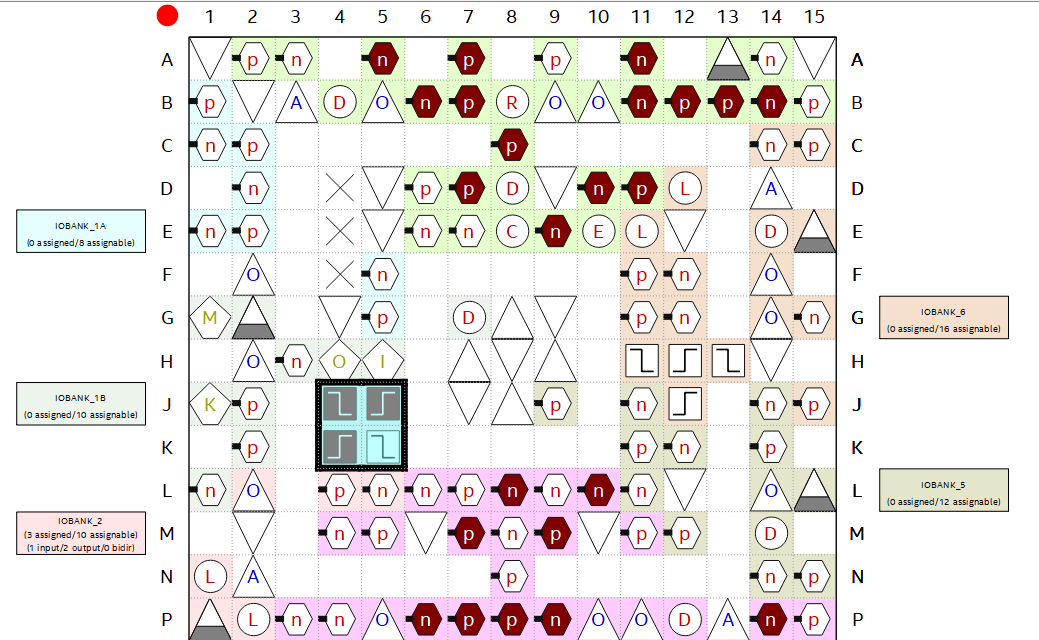
In case of PLL errors - is this because I assigned PLL input / outputs to wrong pin? I am using pins J4, J5, K4 pins for these clocks. input clk is 9.216MHz crystal, output clocks are 18.423 MHz, 2.304 MHz and 384 kHz.
I tried to solve PLL problem by changing mode to "zero delay buffer mode", but then some errors came out:
Error (176557): Can't place PLL "PLL:b2v_PLL|altpll:altpll_component|PLL_altpll:auto_generated|pll1" in target device due to device constraints
Error (176593): Cannot place PLL "PLL:b2v_PLL|altpll:altpll_component|PLL_altpll:auto_generated|pll1" in PLL location PLL_1 -- compensated output clock pin "CODEC_MCLK" of the PLL must be placed in dedicated output clock I/O -- PLL is in zero-delay buffer mode
Error (176568): Can't place PLL "PLL:b2v_PLL|altpll:altpll_component|PLL_altpll:auto_generated|pll1" in PLL location PLL_1 because I/O cell CODEC_MCLK (port of type CLK of the PLL) has an incompatible location assignment with PLL I/O pin Pin_P2
Error (171000): Can't fit design in device
I'm not sure why am I getting error Warning (169202). I set VCCIO of all available banks to 3.3V. All I/Os are set to 3.3V LVCMOS standard (including clock pins)
