Forum Discussion

Altera_Forum Honored Contributor
11 years agoHonored ContributorBPSK Demodulation
Hello again, I am still struggling with BPSK demodulation :)
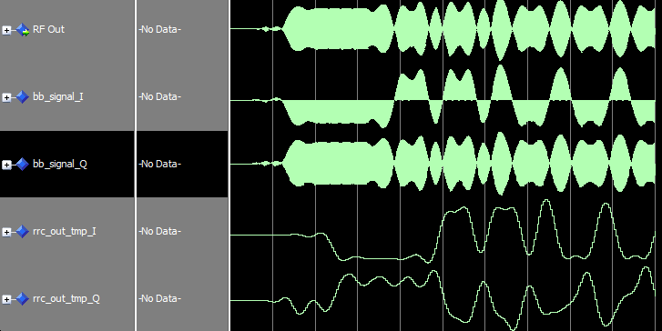
OK, now I am trying to implement Costas Loop for carrier synchronization, which involves Inphase and Quadrature Phase paths. Inphase is looking good, and works as expected, however, the Q component looks awkward. Take a look at these waveforms: http://www.alteraforum.com/forum/attachment.php?attachmentid=10363&stc=1 I understand that multiplying sin * cos will produce a high frequency component, which is a sin modulated by half amplitude of the data signal. BPSK(t) * sin(2*pi*f*t) = 0.5 * [DATA(t) * sin(0) + DATA(t) * sin(2*pi*f*t)] => 0.5 * DATA(t) * sin(2*pi*f*t) => LPF{0.5 * DATA(t) * sin(2*pi*f*t)} = 0 I feel that problem is in my LPF. I used the same Matched RRC filter that I used in the in-phase arm. Papers I read didn't mention that these two filters should be different, that's why I used the same filter. (I think those are unpractical DSP writers, KAZ :D ) So, should I use a separate Loop Filter for Q component? How do I determine it's parameters?66 Replies
 Altera_Forum
well I finally tried my muscles. There is some life in it but it requires a lot of tweaks. It lloks it is tending to lock but requires very long stime so I tried 6000 samples.
clear all; close all; clc; N = 6000; h = fir1(100,0.3); rf_signal = cos(2*pi*(0:N-1)*0.1); %.1,.11,.09 bb_sig = zeros(1, N); y_f = zeros(1, N); error_sig = zeros(1, N); error_f = zeros(1, N); %PLL fs = 1; f = .1; phi_inc = f/fs; for i = 1:N %Downconverting to Baseband bb_sig(i) = rf_signal(i)*exp(j*2*pi*i*phi_inc); %Filtering y_f = filter(h,1,bb_sig(1:i)); %Error error(i) = real(y_f(i))*imag(y_f(i))/2^16; phi_inc = phi_inc - error(i); temp(i) = phi_inc; end plot(temp,'.-'); figure; plot(error); figure; plot(real(y_f(end-1000:end)),'.-');- Altera_Forum--- Quote Start --- Nothing changed also! --- Quote End --- Now what I said should apply but as follows: phy_inc should settle to 0.1, 0.11 and 0.09 for the three cases. I & Q should be dc only in all three cases especially towards end of vector if lock occurs. error may oscillate initially. Do not kill the error by that scaling, you need a target of .01 be added or subtracted from nco value of 0.1 initially. Once the nco is set to this correct value then the error I think will tend to drop towards zero. 200 x 2 does not mean nesting. I simply meant resource of two flters each 200 taps so it 200 x 2 (one per branch) use y = filter(LPF,1,x(1:i)); if it doesn't cut the high band then check response.
- Altera_Forum--- Quote Start --- correction: can you set RF signal to 0.1, 0.11,0.09 and keep nco at 0.1 --- Quote End --- Nothing changed also!
- Altera_Forum--- Quote Start --- correction: can you set RF signal to 0.1, 0.11,0.09 and keep nco at 0.1 --- Quote End --- I will try now. --- Quote Start --- also why you have nested your filter function twice? --- Quote End --- Because you said to filter 200 taps x 2... remember? By the way I tried to filter once... I just got a high frequency component.
- Altera_Forum
I rerun the code without killing the error and bringing it back to life (as Celine Dion says :P )
But nothing changed... exactly same result. So, it's not behaving as Costas Loop. What do you suggest? I surrender! (Also as Celine Dion says :D ) - Altera_Forum--- Quote Start --- There is no indication of lock. You have killed the error by /1e5 then (5*10^-5) , this adds almost nothing to nco tuning word whose range is 0 ~ +/-0.5 for .1 case error should settle zero and filtered signal should be dc (I think you got that because error is forced to nothing) for .09 and .11 case error should settle at .01 (either plus or minus) and filtered signal should be dc (not sine wave) --- Quote End --- correction: can you set RF signal to 0.1, 0.11,0.09 and keep nco at 0.1 also why you have nested your filter function twice?
- Altera_Forum
There is no indication of lock.
You have killed the error by /1e5 then (5*10^-5) , this adds almost nothing to nco tuning word whose range is 0 ~ +/-0.5 for .1 case error should settle zero and filtered signal should be dc (I think you got that because error is forced to nothing) for .09 and .11 case error should settle at .01 (either plus or minus) and filtered signal should be dc (not sine wave) - Altera_Forum
Looks like inverting the sign of imag(carrier) makes everything as you stated!
First, does that mean the model is a correct Costas Loop? Second, why multiply with -imag(carrier) rather than +imag(carrier)? - Altera_Forum
Test fc = -0.09 Error signal:
https://www.alteraforum.com/forum/attachment.php?attachmentid=10391 I feel they are reversed from what you stated they should be. Should I invert the sign of imag(carrier) in code? - Altera_Forum
Alright... I just want to note that the second plots in the above posts are for the phase, NOT the error.