--- Quote Start ---
is your intension to use the epm pins aup and bdown to enable or disable slightly forced rs485 levels into idle levels ? to enshure proper 0 and 1's when not using the rs485 bus ?
your schematic (altium designer?) mentions 5V does this mean your rs485 bus runs at 5v levels between a and b line ?
in addition i fully agree with FvM that you should realy take care about the rs485 levels as the epm240would withstand the emc like a bulletproof 15KV MAX485EESA tranceiver.
between your adlevel 1 -> 0 -> 1 transitions, there seems to be reflection on a and b due to unterminated signals if i interprete these staircases correctly. but what does the blue line mean ? is it the input signal from your tranceiver ?
--- Quote End ---
1.is your intension to use the epm pins aup and bdown to enable or disable slightly forced rs485 levels into idle levels ? to enshure proper 0 and 1's when not using the rs485 bus ?
re:Yes, you are so clever.
2.your schematic (altium designer?) mentions 5V does this mean your rs485 bus runs at 5v levels between a and b line ?
re:1.altium designer8.0(hehe...)
2.the voltage supply of 485 ic is 5VDC.But A line and B line DC voltage level is just 2VDC(in the waveform,it's 2 V/div). Rs485 output is 5V TTL,but i have use other convertor which accept 5V TTL and output 3V TTL to make sure the compatible logic level .
3.what does the blue line mean ? is it the input signal from your tranceiver ?
re:Yes,its the input signal.when it represent wide pulse logic 0(excess 80 ns),i will set the epm240 output with logic 0 or logic 1, other case it will set to logic-Z.
that is
assign aup=adjlevel?1'b0:1'bz;
assign bdown=adjlevel?1'b1:1'bz;
but the result is ...............i can Not get the waveform showed as the waveform i have post. it seem like the 1'bz dosn't work,but the adjlevel signal works ok....
-------------------------------------------------
 Honored Contributor
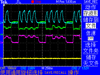