Forum Discussion

 Honored Contributor
BPSK Demodulation
Hello again, I am still struggling with BPSK demodulation :)
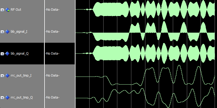
OK, now I am trying to implement Costas Loop for carrier synchronization, which involves Inphase and Quadrature Phase paths. Inphase is looking good, and works as expected, however, the Q component looks awkward. Take a look at these waveforms: http://www.alteraforum.com/forum/attachment.php?attachmentid=10363&stc=1 I understand that multiplying sin * cos will produce a high frequency component, which is a sin modulated by half amplitude of the data signal. BPSK(t) * sin(2*pi*f*t) = 0.5 * [DATA(t) * sin(0) + DATA(t) * sin(2*pi*f*t)] => 0.5 * DATA(t) * sin(2*pi*f*t) => LPF{0.5 * DATA(t) * sin(2*pi*f*t)} = 0 I feel that problem is in my LPF. I used the same Matched RRC filter that I used in the in-phase arm. Papers I read didn't mention that these two filters should be different, that's why I used the same filter. (I think those are unpractical DSP writers, KAZ :D ) So, should I use a separate Loop Filter for Q component? How do I determine it's parameters?66 Replies
 Altera_Forum
looking back at my file it seems I have not completed the loop. (or left it open for some reason).
You will need the final value of carrier to loop back and reapply to input (update input). Thus the second sample when i = 2 will come from new updated vector coming from mixing carrier with signal and so on. Thus I update whole vector each time. This may not very efficient as you can update one sample at a time as well.- Altera_Forum
You will need an indexed feedback loop that acts on one sample at a time fully modelling from input to output. The filtered error together with any proportional element have to be taken care of.
I have attached some old work. This was my initial attempt for qpsk/16QAM (I have lost everything else afterwards). It may not be that correct but should give some idea. It starts with modelling TX side to generate a signal (you may not need that) but focus on the loop. At this point you can try Modelsim before Matlab as it easier there. If you get in difficulty then you better model it in matlab. - Altera_Forum
How can I model the feedback to NCO? I am using the generated MATLAB model of Altera NCO.
If you have another way to model it please tell me. I am sorry for all these questions, I hope that you bear with me. Thanks Mr Kazem. - Altera_Forum
The first part should be:
H(z) = alpha/(1 – (1 - alpha).z-1) There is also + convention for denum term but is confusing Your entry is correct: b = alpha; a = [1, -(1-alpha)]; check it is LPF: freqz(b,a); - Altera_Forum
Very well...
Let's take your suggestion for now. I am trying to implement it in MATLAB, what I'm doing is evaluating the transfer function and I got this: H(z) = alpha/[1+(alpha-1)*z^-1] Is it correct? Then I chose a value for alpha = 0.1 finally I am filtering using this commad: b = [0.1]; a = [1 -0.9]; err = filter(b,a,error_sig); where error_sig is the output of the error detector. Please confirm my work if it's correct. - Altera_Forum
That equation (I am not aware of) could be helpful. What I am suggesting is keep your controls as variables and change then till you get a lock and then keep them
If you want to follow the diagram you posted that is ok. C1 corresponds to scale factor on input and so keep it variable and start with the above equation value. C2 is a scale factor on input to integrator and there is no scale factor on feedback term. You can try that and keep C2 also variable. My IIR suggests a further scale factor on feedback term equal to (1-alpha) producing a typical IIR with unity dc gain. Your case does not care about filter dc gain and it may well work or get out of control. I suggest you add scale factor on feedback term and set to 1 if it turned out to be irrelevant. Thus the IIR cutoff is under control of these variables and these variables will eventually be fixed in design by trial and error. I don't know what is PI (proportional Integrator?).Yes we are talking about same thing but I am conceptually splitting the single system into two. - Altera_Forum
I did the LPFs that attenuate the f1+f2 components, and it filters perfectly (Using 200 taps x 2).
Now, I am confused with the loop filter (IIR filter). Many texts suggest using the proportional-integral control technique that I attached before. I believe you are referring to the same thing except that yours has no proportional part (and you suggest to add it later if needed). It has this transfer function: H(z) = c1 + c2/(1 - z^-1) where c1 = 4*(theta)^2/(1+sqrt(2)*theta+theta^2) and c2 = 2*sqrt(2)*theta/(1+sqrt(2)*theta+theta^2) where theta = 2*pi*BW, BW is bandwidth of the filter in Hz. Let me ask you some questions: 1- How to determine the cutoff frequency of this filter, regardless of the structure. 2- Is leaky integrator the same as PI technique? How different they are? I think I have more questions but they relate to your answers of these. - Altera_Forum--- Quote Start --- That's great! But, would you please explain what "200 taps x 2" mean? --- Quote End --- two filters each 200 taps
- Altera_Forum
That's great!
But, would you please explain what "200 taps x 2" mean? - Altera_Forum
for IIR you may try the leaky integrator:
y(n) = alpha.x(n) + (1-alpha).y(n-1) (requires two mults) or its equivalent of one mult: y(n) = alpha.[x(n) - y(n-1)] + y(n-1) alpha will give you you control of cutoff but dc gain will stay unity (alpha = 0~1 normalised) you can also use power of 2 value for alpha to avoid that single mult if such cutoff resolution is enough. if required you can also increase/decrease dc gain (apart from cutoff) by scaling input as per your diagram or dividing final output by truncation. For f1+f2 frequency filtering you need to attenuate it enough e.g. by 40dB. 200 taps x 2 sounds way too much. You don't need to cutoff that sharp since the sum term will be at some distance and assuming you don't have much noise in your signal or that it can be filtered by rrc. I personally believe you better use rrc inside the loop for this purpose.