Forum Discussion

Altera_Forum Honored Contributor
11 years agoHonored ContributorBPSK Demodulation
Hello again, I am still struggling with BPSK demodulation :)
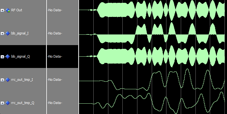
OK, now I am trying to implement Costas Loop for carrier synchronization, which involves Inphase and Quadrature Phase paths. Inphase is looking good, and works as expected, however, the Q component looks awkward. Take a look at these waveforms: http://www.alteraforum.com/forum/attachment.php?attachmentid=10363&stc=1 I understand that multiplying sin * cos will produce a high frequency component, which is a sin modulated by half amplitude of the data signal. BPSK(t) * sin(2*pi*f*t) = 0.5 * [DATA(t) * sin(0) + DATA(t) * sin(2*pi*f*t)] => 0.5 * DATA(t) * sin(2*pi*f*t) => LPF{0.5 * DATA(t) * sin(2*pi*f*t)} = 0 I feel that problem is in my LPF. I used the same Matched RRC filter that I used in the in-phase arm. Papers I read didn't mention that these two filters should be different, that's why I used the same filter. (I think those are unpractical DSP writers, KAZ :D ) So, should I use a separate Loop Filter for Q component? How do I determine it's parameters?66 Replies
 Altera_Forum
Hi, KAZ.
I modeled it in MATLAB. After converting to DC, I am filtering using a FIR filter that utilizes Hamming window. The output of the filters are not clear of f1+f2 though! High component frequency is just attenuated, is this the purpose or I need to completely eliminate it? If I need so, filter required is of order 200+!! I think that's very much resource consuming when it's ported to FPGA, right? Regarding IIR filter, how do I design it? Do I use fdatool in MATLAB? or the structure I attached above is good?- Altera_Forum
The bb_I difference from bb_Q may be due to your nco phase. For now assume it is ok and focus on cutting off the f1+f2 term in each branch.
The wanted signal will move close to dc and depending on your signal bandwidth. you need to cutoff clear of your signal bandwidth but kill the f1+f2 copy. So far you have downconverted your signal to dc but now and since signal centre may shift either side of dc due to uncertainties of oscilillators bewteen Tx and Rx you need to force it to dc all the time. The error detector is just a multiplier as you have found out. apply IIR LPF (integrator) to the error as it will be very noisy. The gain of IIR need to be manually adjusted until error shows dampened oscillations heading towards zero with some jitter. For testing you will need to move your RF centre either side and see that the loop does not lose lock otherwise the radio user will have to keep adjusting the tuning knob and lose interest in music. If your loop fails to lock try adding the proportional term to the output of IIR through a scaler that can be adjusted. - Altera_Forum--- Quote Start --- You need one filter per branch to remove the f1+f2 (sum term) leaving signal at dc (f1-f2). Any LPF will do (including rrc if you wish). The loop itself needs error detector and filter to smooth out the error. This loop filter can be an IIR with variable gain. The IIR filter represents the integral part of your loop control system. You may need further control terms such as proportional term. The filter error is then used to shift phase(or frequency) of NCO in the opposite sense. --- Quote End --- The error detector you referred to is the mixer at the end of the loop, right? Regarding loop filter, I saw some structures that combine both integral and proportional terms, is it the same as you are suggesting? http://www.alteraforum.com/forum/attachment.php?attachmentid=10367&stc=1 --- Quote Start --- I notice your bb_signal_I has plenty of zeros in it but not Q --- Quote End --- You mean zero crossings? is this bad? --- Quote Start --- I wouldn't advice you to do any decimation inside loop as it could get complicated on you. --- Quote End --- I thought decimating is beneficial before doing any further signal processing as this relaxes the requirements. I'll use regular LPFs then. How to choose the cutoff frequency of these LPFs?
- Altera_Forum
You need one filter per branch to remove the f1+f2 (sum term) leaving signal at dc (f1-f2). Any LPF will do (including rrc if you wish).
The loop itself needs error detector and filter to smooth out the error. This loop filter can be an IIR with variable gain. The IIR filter represents the integral part of your loop control system. You may need further control terms such as proportional term. The filter error is then used to shift phase(or frequency) of NCO in the opposite sense. It takes sometime for the loop to lock. You observe the error and this should converge and settle with low jitter. I notice your bb_signal_I has plenty of zeros in it but not Q I wouldn't advice you to do any decimation inside loop as it could get complicated on you. - Altera_Forum
I am sorry, it's my mistake... I didn't mention that after multiplication there is CIC filter... before RRC.
So these are the waveforms: https://www.alteraforum.com/forum/attachment.php?attachmentid=10365 Basically, I am trying to design this loop: https://www.alteraforum.com/forum/attachment.php?attachmentid=10366 Instead of LPF, I used CIC filters, as they do filtering and decimation at the same time. Am I wrong? You are right, RRC has nothing to do with Costas Loop. - Altera_Forum
How did you design the costas loop? How do you control the loop>
loop filter has to be separate filter from rrc. You will use it to control the lock of your costas loop and usually a simple IIR will do I have used rrc after costas locking section but I know some do it before but not as loop filter (there are different rx configurations and you better model it matlab before going to hardware).